
I have an automatic garage door opener, but no safety beam unit (which stops the door if an obstruction breaks the beam) so I built one myself.
My garage door opener has one pair of terminals marked 'Transmitter' and one pair marked 'Receiver'. I assumed that the transmiter pair was simply a power supply, and the receiver pair would accept a Normally Closed input. Testing confirmed this, with 15VDC on the transmitter, and a link busbar on the receiver terminals which I removed.
I decided that the simplest method would be to use a minature laser-diode as the transmitter, and an infra-red phototransistor as the receiver. (Although the lasers emit visible light, they seem to also emit enough IR light to switch an IR phototransistor.) I bought a couple of the small 'bullet' style laser pointers for £2 each (one left over for some future project!) and removed an IR transistor from a dead mouse I had.
The transmitter unit was the easy part. I extracted the laser-diode from the bullet pointer, and mounted it in the lid of a small plastic project box. It has a screw thread on the barrel so it simply screwed into the hole I drilled. The only extra component needed was a low current 5V regulator so I could run the laser from the 15V of the door opener unit. I used a 78L05 3 pin regulator.
Transmitter inside view:
![]()
However, I came across a problem that when I tried to draw any current from the door opener transmitter pair, the voltage dropped to an unacceptable level. After carrying out some tests I found that only around 7mA was available from the supply! That is no use to man or beast so I opened up the opener (!) and reconnected the transmitter supply to what seemed to be the main unregulated supply from the PSU (approx 15-20VDC) through an inline fuse. This solved the problem.
The receiver unit runs directly on the unregulated power from the door opener as the voltage is not critical. The phototransistor switches the base of a small NPN bipolar transistor, which in turn controls a relay. The relay contacts are then wired back to the receiver pair on the door opener. I added an LED which illuminates when the beam is detected to help with the alignment process.
Receiver inside view:
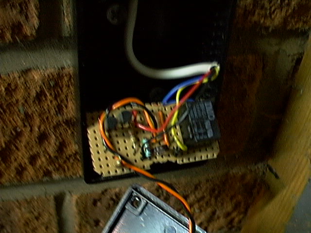
Pictures of completed transmitter and receiver below. The alignment of the transmitter needs to be fairly accurate, you can see I have used wedges to adjust this. Of course a proper adjustable mount would be a better solution, but this is a DIY job! The laser diode modules have a focus adjustment by rotating the lens so the spot diameter can be increased slightly, easing the alignment process.

![]()
![]()
![]()