
I wanted to build a two-level control panel based on the Supercade panel.
I ordered an I-PAC4, and a bunch of buttons from Ultimarc, and the 4 joysticks from Happ Controls Europe as Ultimarc don't do the whole range of colours.
3" Betson Imperial trackball came from Todd at TNT Amusements, ex-Golden Tee.
 |
I designed the control panel layout using Visio. Although it pains me to use Microsoft products, it's actually not bad. I printed out a full size version on an A0 plotter, so I could use it as a guide for drilling the holes on the panel. |
 |
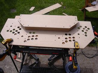
The overlay taped to my 9mm panel cutout. I made a mistake when I modified the Supercade plans - as the UA2 control panel support is actually deeper I had to recut the control panel a couple of inches deeper. I drilled through each button, joystick and trackball posistion with a 3mm bit for a pilot hole. I then removed the overlay and drilled through the buttons with a 28mm spade bit, and the joystick holes with a 25mm spade bit. |
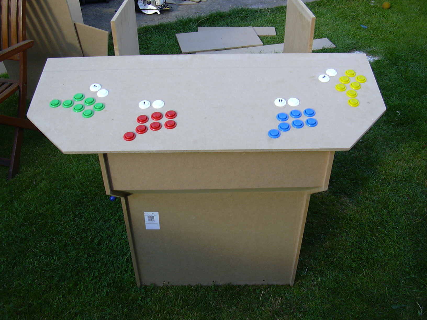 |
I put the buttons in just to see what it might look like. |
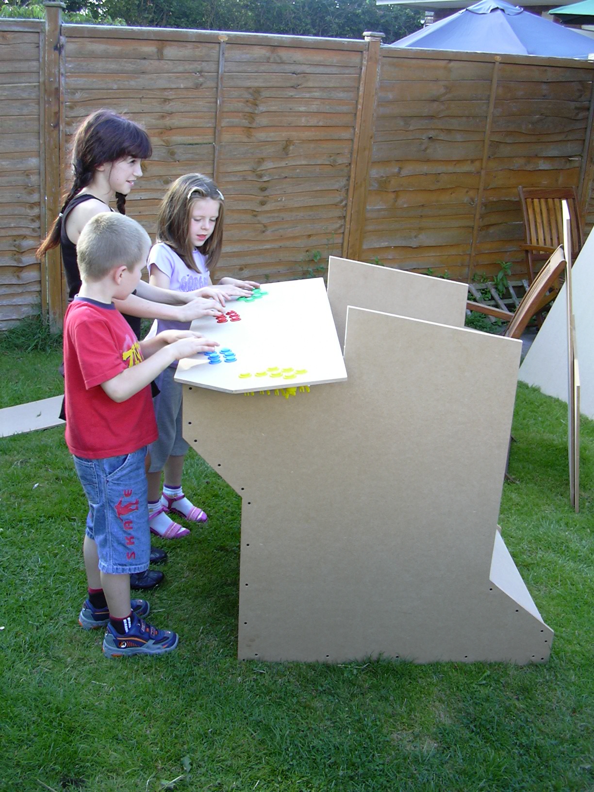 |
Here's a bunch of kids testing it out. Have they figured out it doesn't work yet?
|
 |
I then cut out the pieces for the top deck of the control panel. The top is 9mm MDF and the thin vertical peices are 12mm. |
 |
A section of the bottom deck is cut out with a jigsaw where the top deck will attach. |
 |
The peices are assembled using furtniture screws into pilot holes and countersunk. |
 |
The view from underneath. |
Trackball mouse hack
The basic trackball has no interface circuitry to connect directly to a computer, it simply outputs the raw quadrature encoded signal from the optical encoder wheels. To connect this to the computer we can hack a mouse, either PS/2 or USB. I used a spare Microsoft PS/2 mouse that I had:
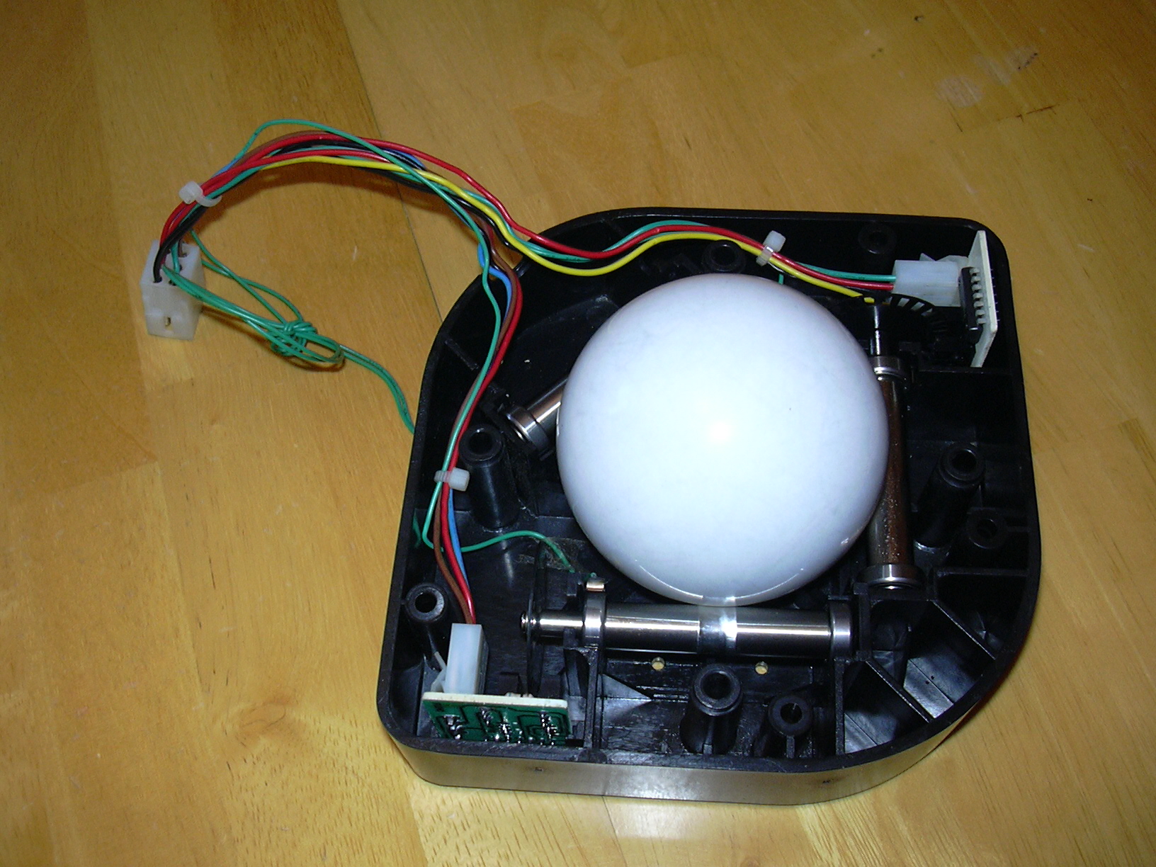 |
Betson Imperial 3" trackball with top cover removed. You can see the bottom roller has worn quite a bit and needs replacing. It still works OK though for now. |
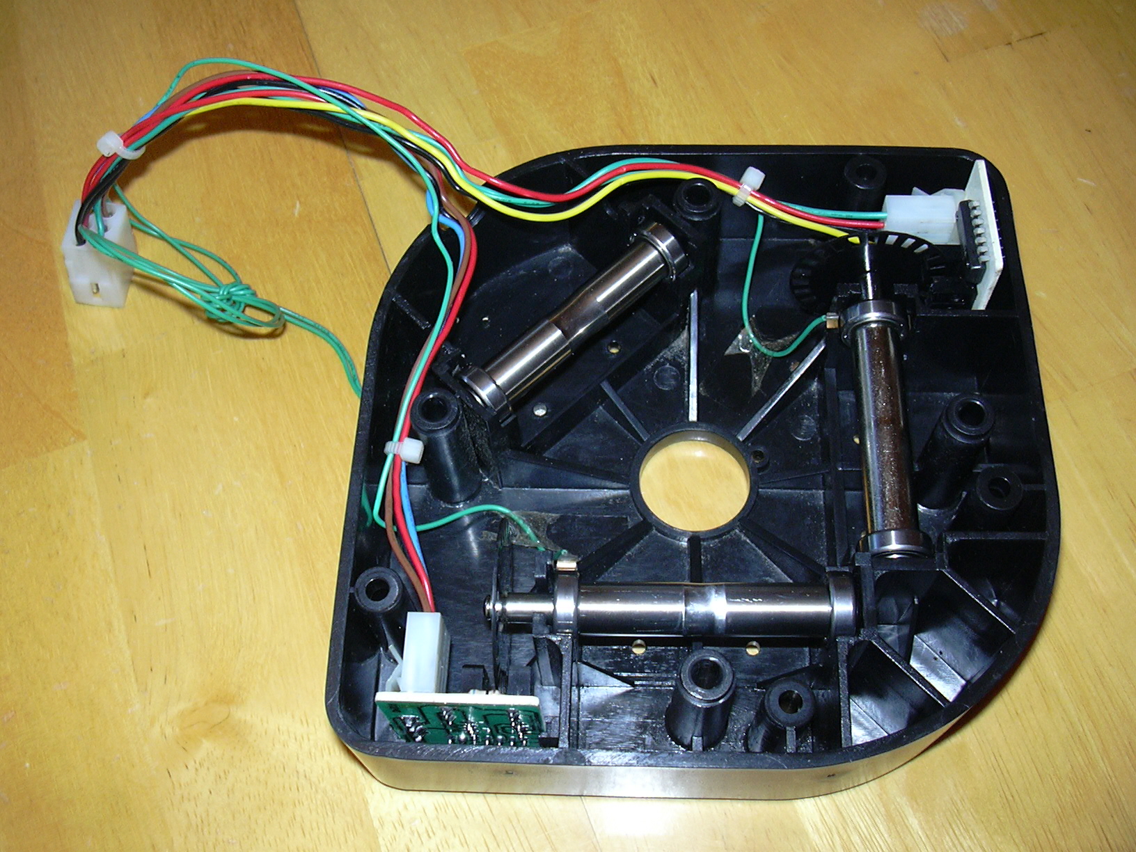 |
Ball removed. |
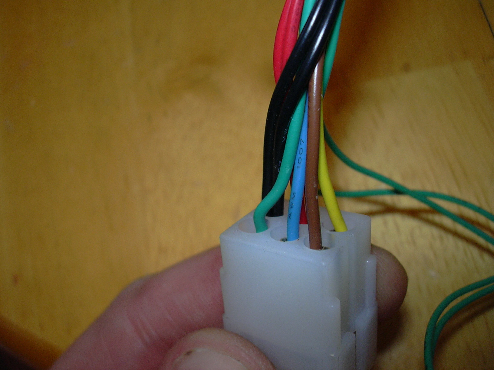 |
The trackball connector needs to be cut off and the wires stripped and tinned. |
 |
The PCB is removed from the mouse. On the left are the three button microswitches and the scroll wheel opto. Slightly to the right of centre at the top and bottom are the two optos for the X-Y that must be unsoldered. |
 |
Here you can see I have removed the 2 opto-transistors (Q1 & Q2) and 2 IR emitters (D1 & D2). |
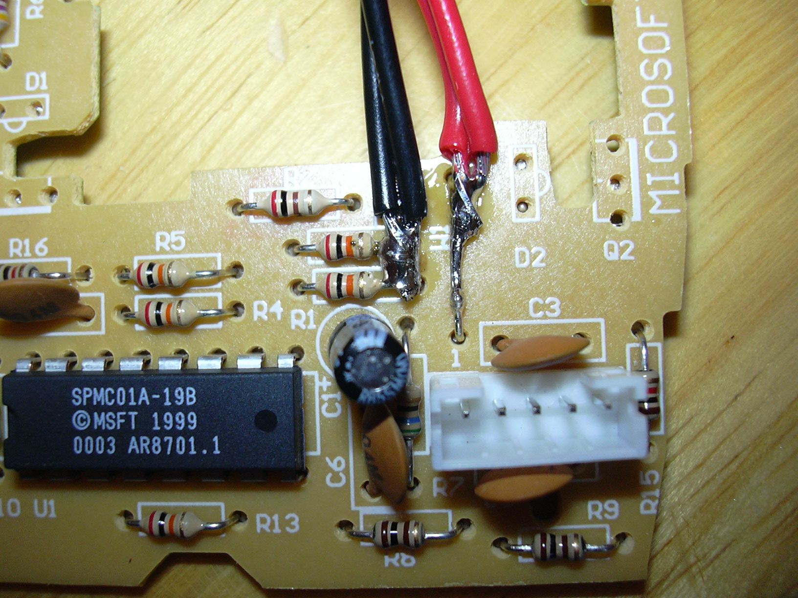 |
The trackball requires +5V power which we can get from the mouse. Solder the red and black trackball wires as per the diagram. The right-hand side of the two resistors were already connected together by a track on the PCB. |
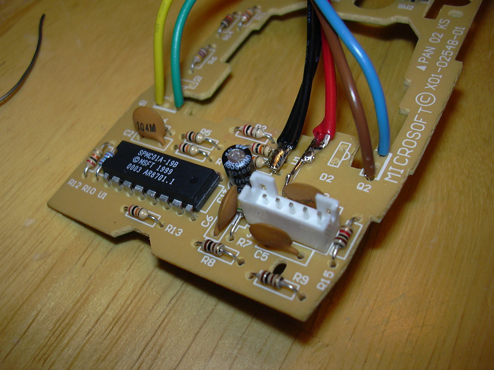 |
Next the 2 pairs of X-Y wires need to be connected where the opto-transistor output pins were. The trackball can now be tested by reconnecting the PS/2 cable to the mouse PCB and plugging into a computer. The first time I tested it one of the axis was reversed, but that is easily corrected by reversing the wires within a pair - e.g. swap brown and blue, or green and yellow. |
 |
I wanted the PCB to fit inside the trackball housing, and as I didn't need the mouse buttons or scroll wheel inputs I cut off the top half of the PCB with a pair of side cutters. It still works perfectly! |
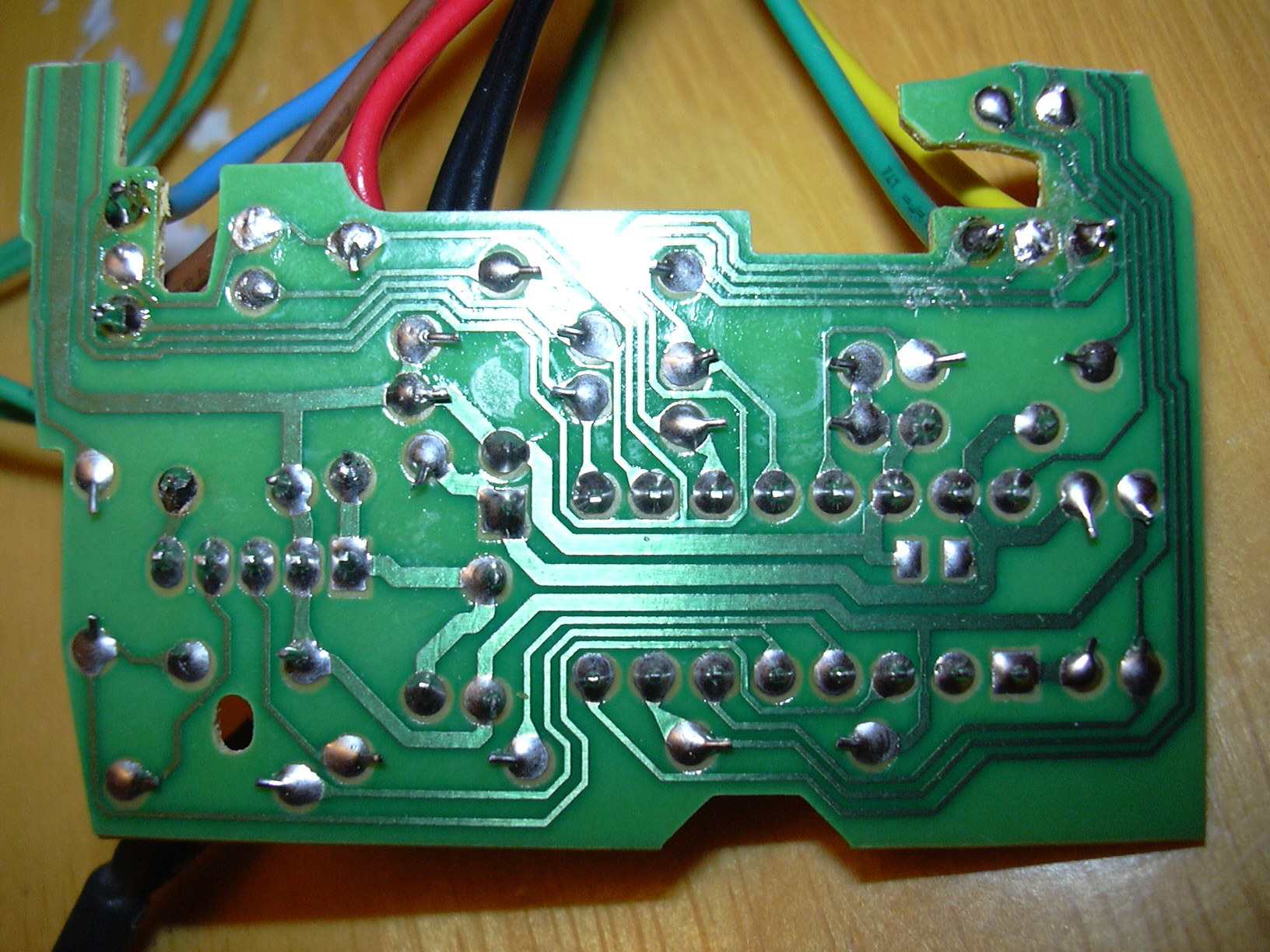 |
View of the underside of the PCB. |
 |
PCB fits inside the trackball nicely. |
 |
And the final product, a PS/2 trackball. There is no backspin whatsoever, even when spinning the ball as fast as possible. (Backspin occurs when the decoder interface cannot keep up with the speed of the pulses from the encoder wheels, and the pointer moves erratically, usually backwards) |
Trackball mounting.
One way to mount a trackball is to use a trackball mounting plate which can be got from Happ Controls etc. However I thought of an alternative way which would eliminate the need for a mounting plate, and would allow the ball to sit higher out of the panel.
Here is a diagram of a trackball with a mounting plate (which you can't see):

So I thought why not remove the top cover of the trackball:

And mount it with long screws and spacers directly:

I tried this on a test piece of MDF cutting a hole with a holesaw, then chamfering the edges with my router. It seemed like it would work OK, but I would need to route out slots for the PCBs and encoder wheels but thats no big deal.
 |
The hole was cut with a 2 7/8" holesaw. I clamped a scrap piece underneath with an identical hole for the guide pin on the router bit to ride. It's easy to adjust the final hole diameter by adjusting the depth of the chamfer bit in the router. I may need to route a slightly larger hole when I add the acrylic overlay to the top of the 9mm MDF control panel - I can just reroute it a little deeper. The PCB/encoder slots were done with my 12mm straight bit - you can see it went a bit wonky on the bottom one where I didn't clamp my guide tight enough. |
 |
The trackball base was then attached using 75 x 5mm screws, using 1 nut and 2 washers as standoffs to get the height correct to give a neat fit on the top. Again, I may need to adjust this when the CP overlay is added. |
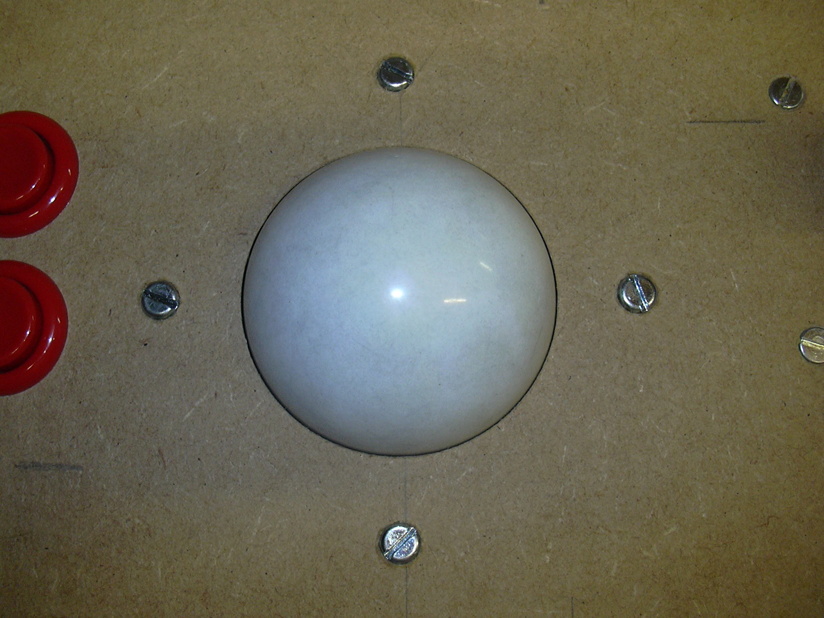 |
And this is what it looks like from the top. It spins nice and freely, there is only a very tiny gap around the sides. |
 |
I think it protrudes from the control panel much more than you would get with a mounting plate. You might notice the screws are not countersunk - this will be fixed when I find some long countersink screws, or I'll just recess these ones a little. |
Wiring the Control Panel
For the control panel wiring I used 1/4" crimp quick-disconnects with a ratchet crimper, and 0.2mm/7 strand cable. I ran separate grounds from each players set of controls to the IPAC, which should make fault-finding easier.
 |
Just starting out. I tried to use a different colour for each button, although I did have to duplicate a couple when I ran out of colours. Each ground is looped through each microswitch on the controls for each player. I cable-tied the wires for each set of player controls separately and used P-clips to secure to the underside of the control panel. |
 |
And here's the wiring complete (sort of). As you can see the IPAC is not yet secured to the base. |
 |
A closer view of the wiring. |
Flight stick mounting.
Gildersneeze on the BOYAC forums recommended the Saitek ST-90 USB flight stick. Because the gimble is in the handle rather than the base it is very easy to mount:
 |
The Saitek ST-90 has three fold up 'legs', which lock into place by a rotating orange collar. The legs can be removed with an allen key, and the orange collar removed by taking out the 4 screws in the base (under the sticker). |
 |
The three leg brackets are chopped off with a junior hacksaw. |
 |
And sanded smooth, The base will now fit into a 40mm hole. |
| I cut a 40mm hole in the top deck of the control panel, and also in a spacer made from a square of 9mm MDF. Actually I only had a 38mm hole saw, so I enlarged the hole with a sanding bit on my drill. | |
| I cut a slot in the spacer for the cable to fit, and then pushed the joystick into the control panel and spacer. It's a tight fit. | |
 |
I epoxied the orange collar to the removable joystick base so that it no longer rotates, and then drilled each 'fin' on the collar to recieve a mounting screw. This will fasten the joystick to the control panel and stop it moving or rotating. |
 |
The screws fasten the collar/joystick to the spacer and the control panel, with no mounting visible from the top. |
 |
And here's what it looks like mounted. |
 |
Overview of the control panel with the controls in so far. A spinner will be added to the top deck, and I still need to place the admin buttons somewhere... |