
If you want the look of a real arcade
machine you really can't use a standard computer monitor - it just
doesn't look right! Computer monitors are designed to run at higher
resolutions and refresh rates, and the images just look too blocky and
sharp when playing arcade games. The real arcade monitors run at a
horizontal frequency of approximately 15kHz with vertical refresh rates
of around 50 - 60 Hz, and the low resolution means that the raster
lines are visible. The preferred monitor for Mamers seems to be the
Wells-Gardner D9200 - this supports a range of frequencies so can run
games that also use 25kHz and 31kHz horizontal refresh rates.
Unfortunately here in the UK this monitor costs close to £600
including VAT and delivery!
Well thats a bit too expensive for me, so I wanted an alternative, and
luckily there is another common device which also uses a 15kHz sync
frequency - a television! Well when I first heard of this idea I was a
bit sceptical about the image quality that would be achieved. However
in the UK TV's with RGB input via the SCART connection are fairly
common, and I was assured by people on the BYOAC forum that the image quality
using RGB would be just as good as an arcade monitor (essentially using
this method they are identical, the TV just has a tuner and a load of
other stuff that we just are bypassing).
To drive a TV or arcade monitor from a standard VGA graphics card you
need to use special software to ensure the output frequencies are in
the correct range. If you try to output standard VGA frequencies to one
of these devices you can actually physically damage it! I chose
AdvanceMame for this task as that is what it's designed for, plus it
runs under Linux which is my OS of choice.
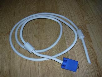 |
You need to make a lead to connect your graphics card to your TV. I cut the VGA lead off a broken monitor. |
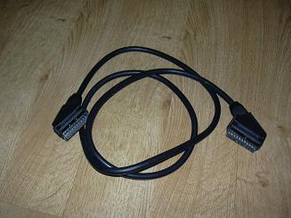 |
I had a SCART lead hanging around, so I cut off one plug, and removed and saved all the pins. |
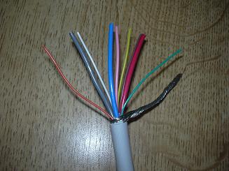 |
The end of the VGA lead is stripped. You can see the Red, Blue and Grey leads are a bit thicker than the rest - these carry the RGB signals, and are individually screened to reduce crosstalk between them. |
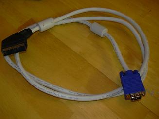 |
I soldered the pins I removed from the SCART lead to the ends of the VGA lead, then reinserted the pins into the SCART plug according to the table below: (note that Hsync and Vsync are combined, as the TV requires composite sync). I added a cable for the 5v to trigger the blanking input - this tells the TV to use the RGB signals on the SCART rather than composite. Not all TVs require this, but the one I bought does. The 12V on Pin 8 makes the TV switch to the AV input automatically. |
|
SCART - VGA lead pin-out
|
||
| Function | SCART | VGA |
| Red | 15 | 1 |
| Green | 11 | 2 |
| Blue | 7 | 3 |
| Red ground | 13 | 6 |
| Green ground | 9 | 7 |
| Blue ground | 5 | 8 |
| Composite sync ground | 17 | 10 |
| Composite sync | 20 | 13 + 14 |
| Chassis ground | 21 | Screen |
| Blanking | 16 | PSU +5v through 100R resistor |
| Blanking ground | 18 | PSU 0v |
| AV select | 8 | PSU +12v |
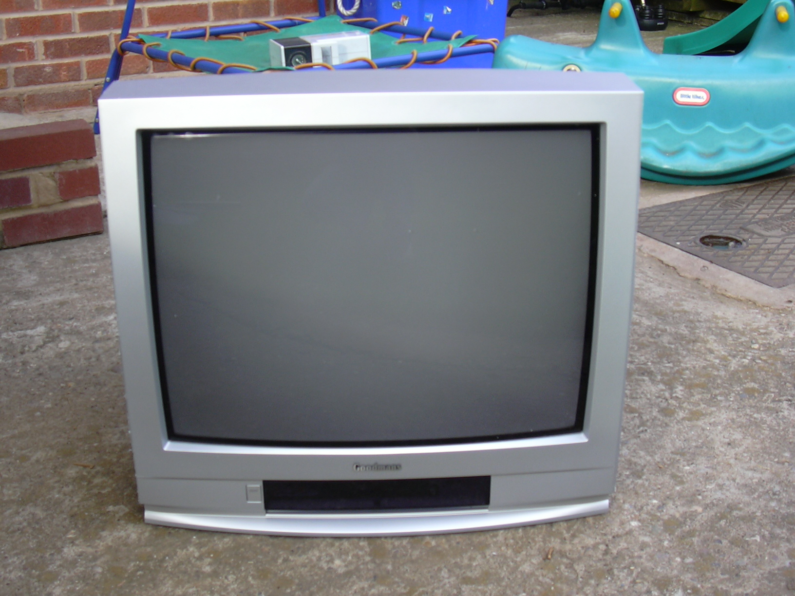
I made my cabinet slightly narrower than the standard Ultimate Arcade 2, at a maximum width of 26 inches. This is so I could get it through the narrowest of the doors in our house. This means that I have an internal width of 25 inches, and the largest TV that would fit comfortably is a 25". This size is fairly uncommon, but Comet sell a Goodmans 258NS for £199. After checking that it supports RGB on the SCART, I bought one. Unfortunately this TV has stereo speakers on the sides, so will not fit in the cabinet (I did know this before I bought it!) - but we don't need those so we chopped them off with a hacksaw:
 |
Here's the TV brand new out of the box. Works great with advancemame using the lead I made above. It does overscan quite a bit, this can be corrected by accessing the TV service menu. The TV is based on the Daewoo CP785 chassis. You can download a service manual for a similar model here which describes how to access the service menu, as follows: 1 - Select pr. number 91 |
 |
The back is removed very easily by removing a few screws. The side speakers unscrew from the case and unplug from the PCB. |
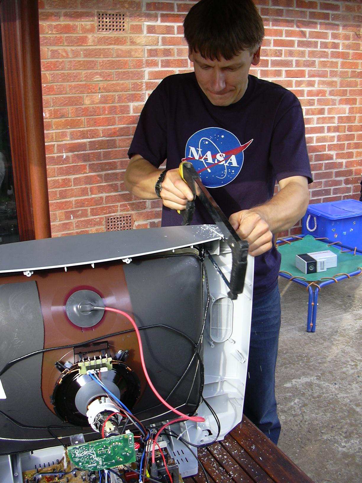 |
Here is my friend Chris cutting the side off with a hacksaw. I think he just voided the warranty! |
 |
We changed to using the hacksaw blade in a padsaw handle to get all the way down the case. |
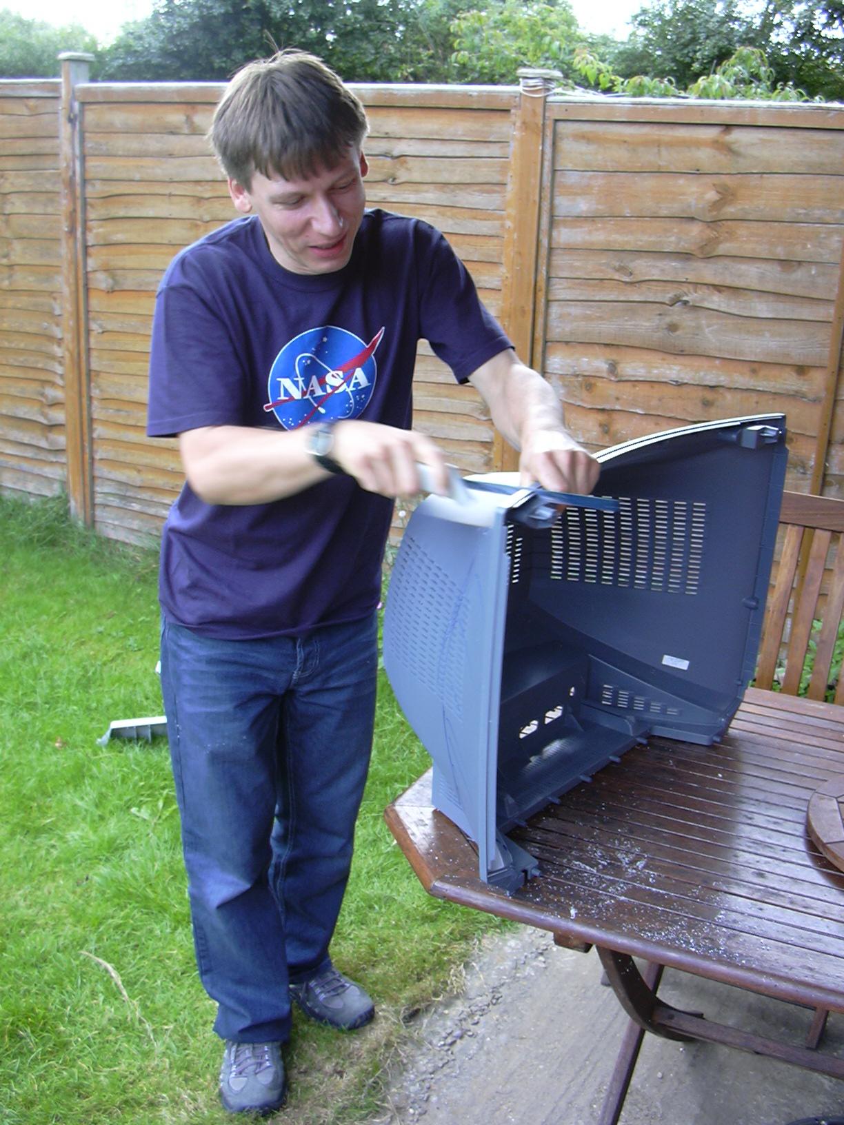 |
The back is cut in the same way. |
 |
TV minus it's 'ears'. |
 |
The finished article - much better! The back is screwed back on, although only 2 of the original screws actually screw into anything now, so we drilled the bottom and used 2 x 4mm screws and nuts to hold it together securely. |
 |
Side view with back on. |
 |
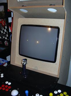
And here it is in the cabinet. Of course I still need to sort out a bezel, and the monitor shelf needs a couple of battens underneath for support, but we can see that it fits OK! This picture shows 1942, which is a vertical game so we get bars either side of the screen. |
 |
Hey come on guys, who buried the TV?! |
 |
Later I decided it would be best to ditch the TV casing altogether and mount the tube in a piece of chipboard instead to make the whole thing more solid.As you can see it still needs a bezel. |
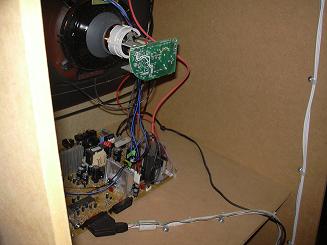 |
View from the rear. The PCB is mounted to the base of the cabinet using plastic hex standoffs and screws in the existing holes in the board. |